Building an LED Circuit#
TODO
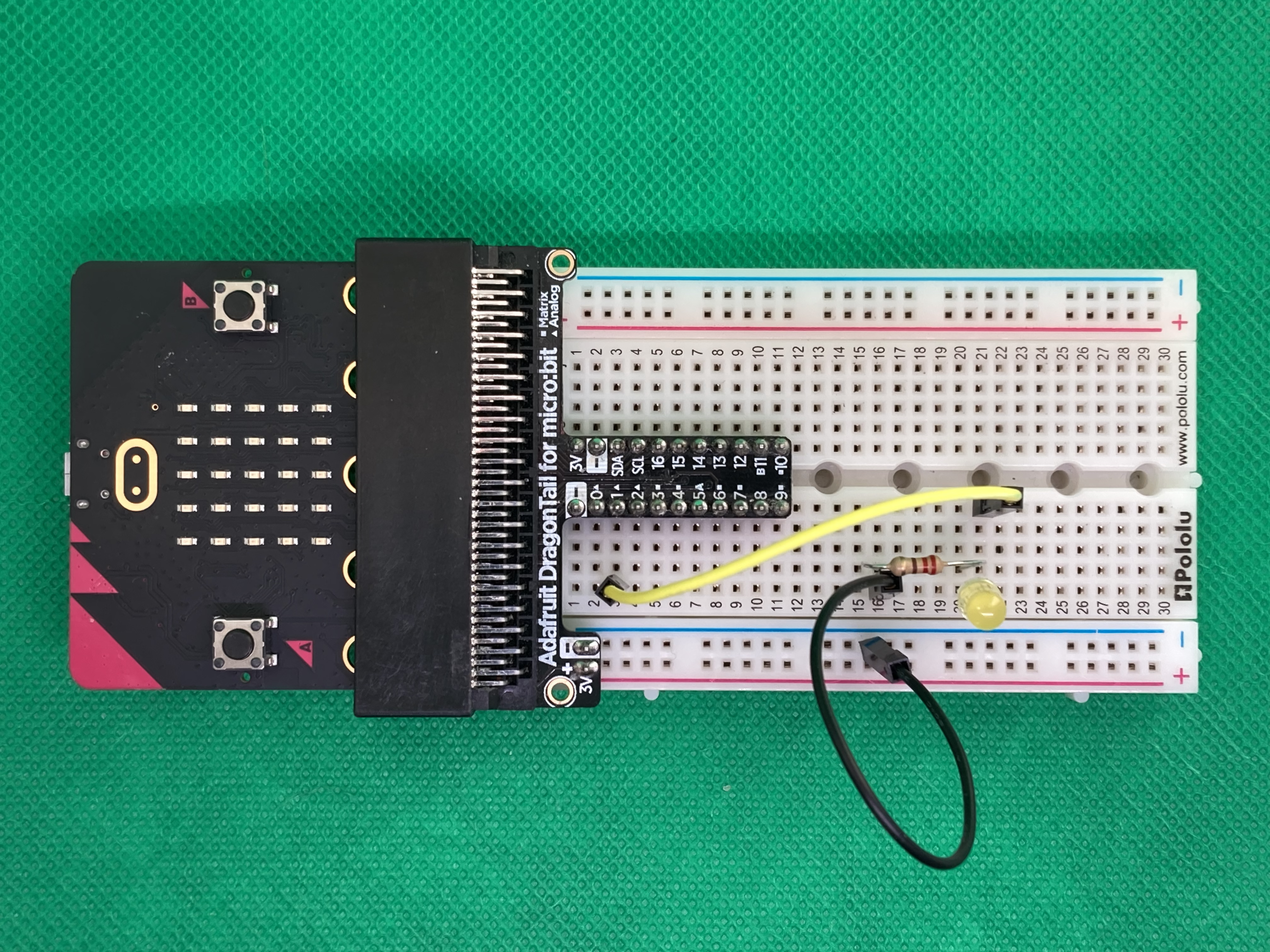
Building an LED Circuit with the Adafruit Dragontail (Or Similar Type)#
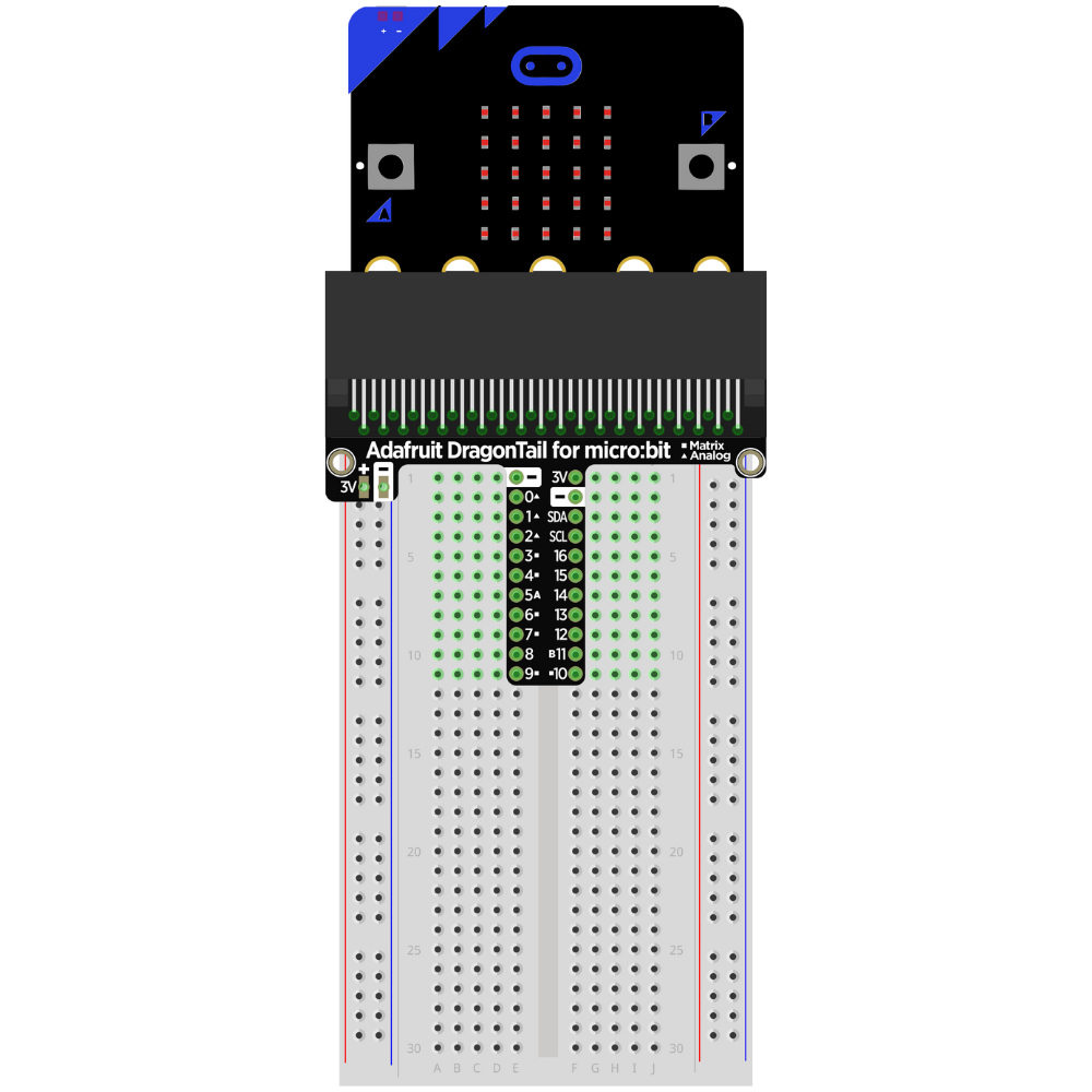
Insert the micro:bit into the micro:bit to the Adafruit Dragontail.
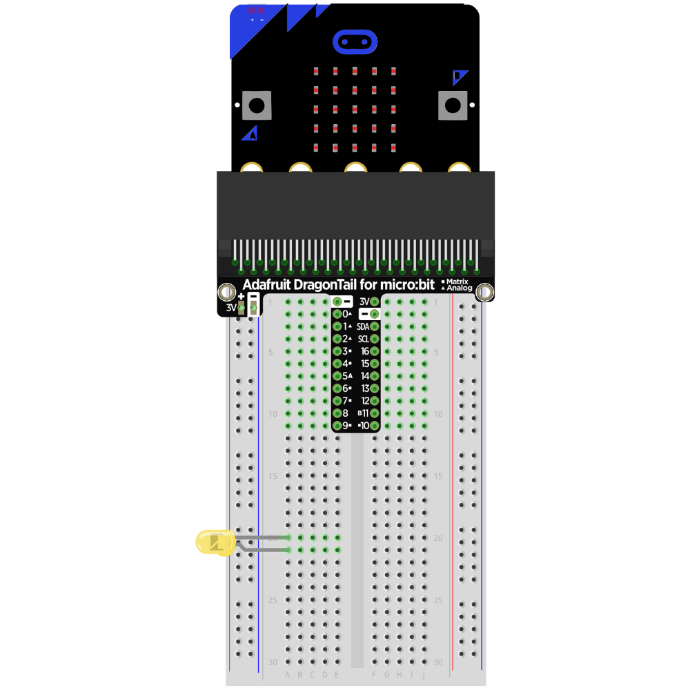
Insert the LED into the breadboard.
**Make sure that the LED and the cathode are not on the same row on the breadboard. **
Take note of which lead is the anode.
Tip
Choose a side that the LED lead will always be facing (right or left). This helps prevent incomplete circuits and makes it easier to remember which lead is the anode and which lead is the cathode.
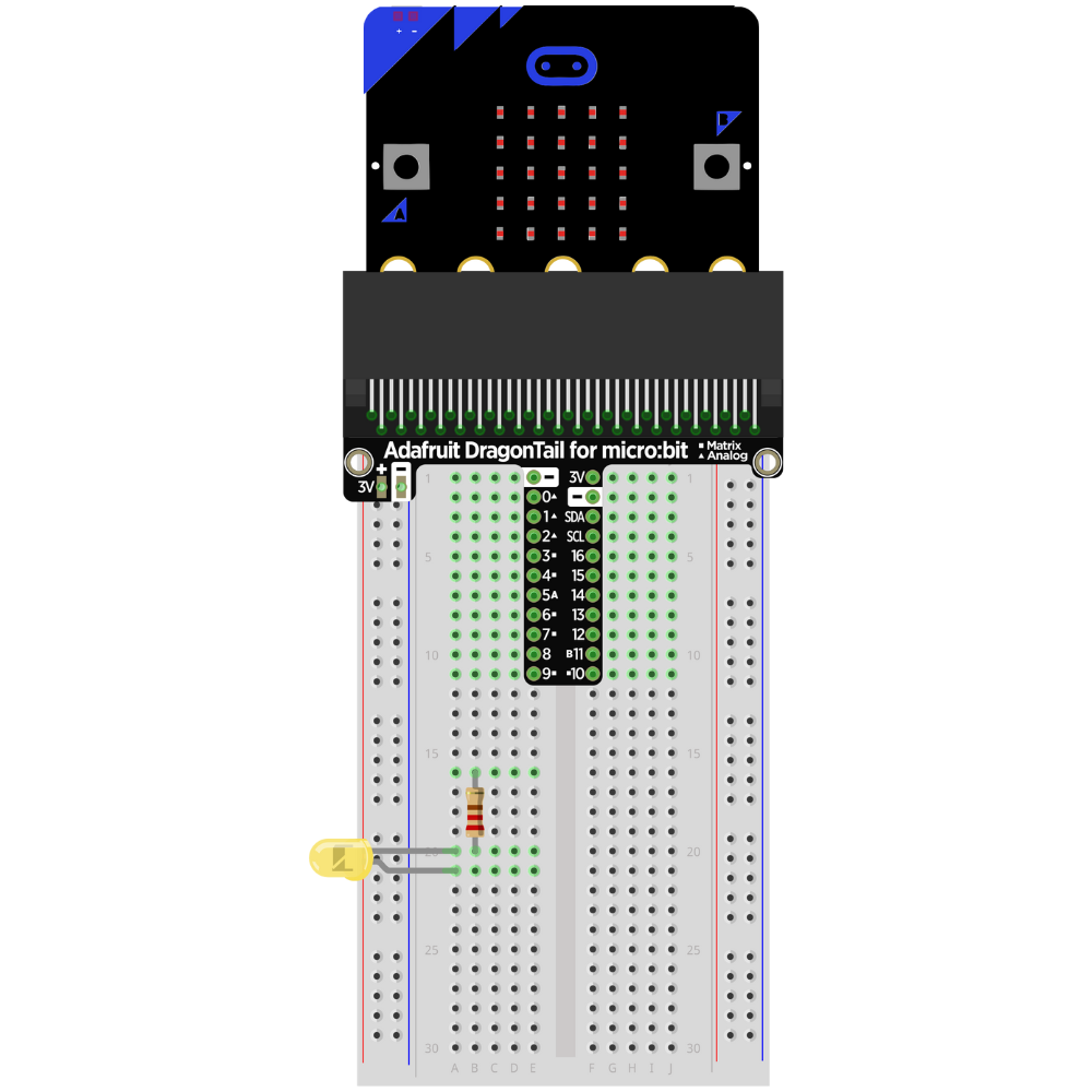
Attach a resistor to the row with the cathode lead of the LED.
Note
The resistor can be attached to either the anode or the cathode in an LED circuit. Pick one lead (either anode or cathode) and attach it to that lead every time an LED circuit is built.
Attach the resistor to the GND rail on the side of the breadboard.
Note
It is also possible to use the resistor as the lead from the GND rail to the cathode.
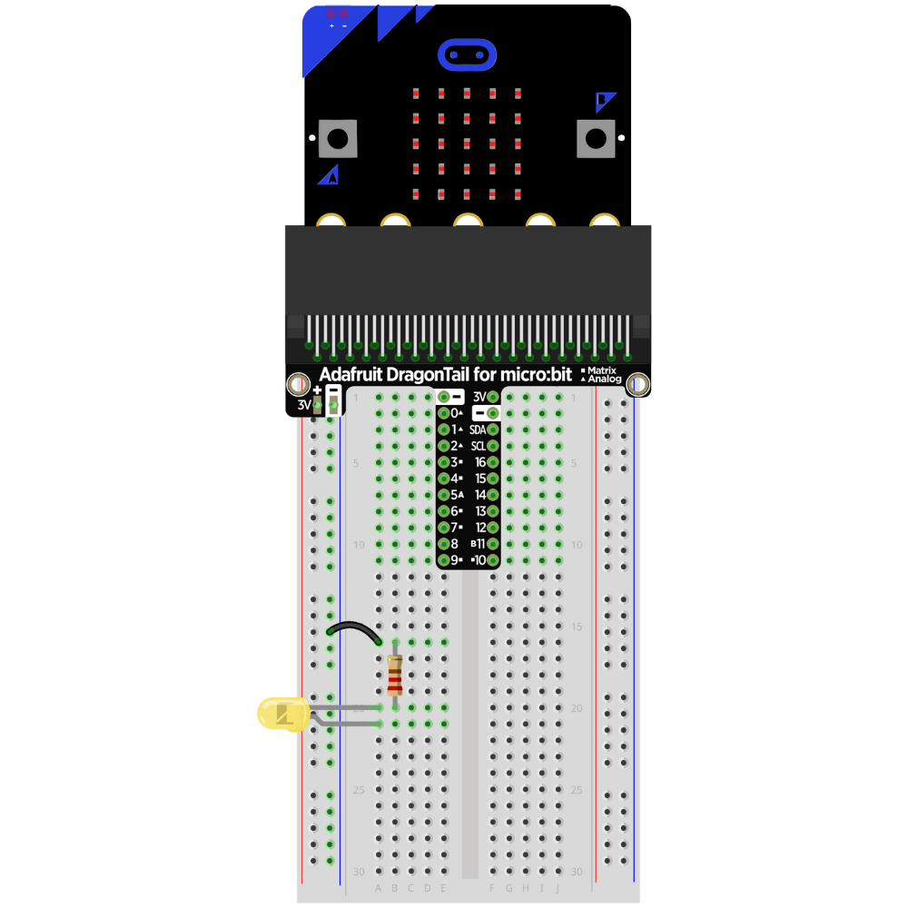
Place a jumper wire from the row attached to Pin 1 to the row with the anode.
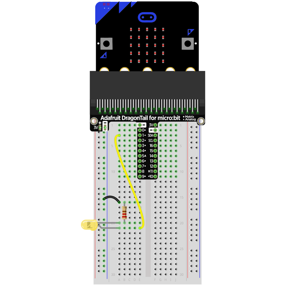
The circuit is complete.
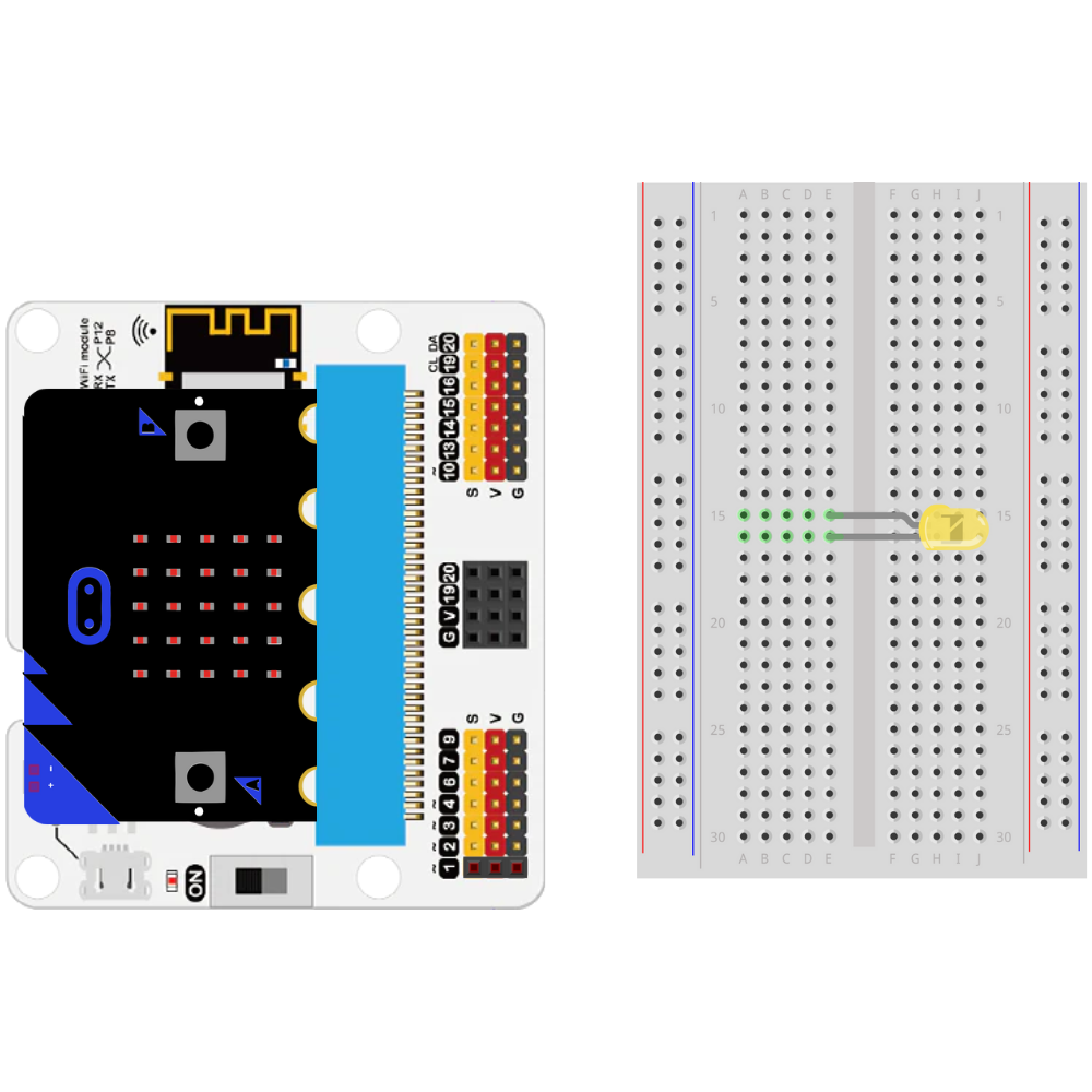
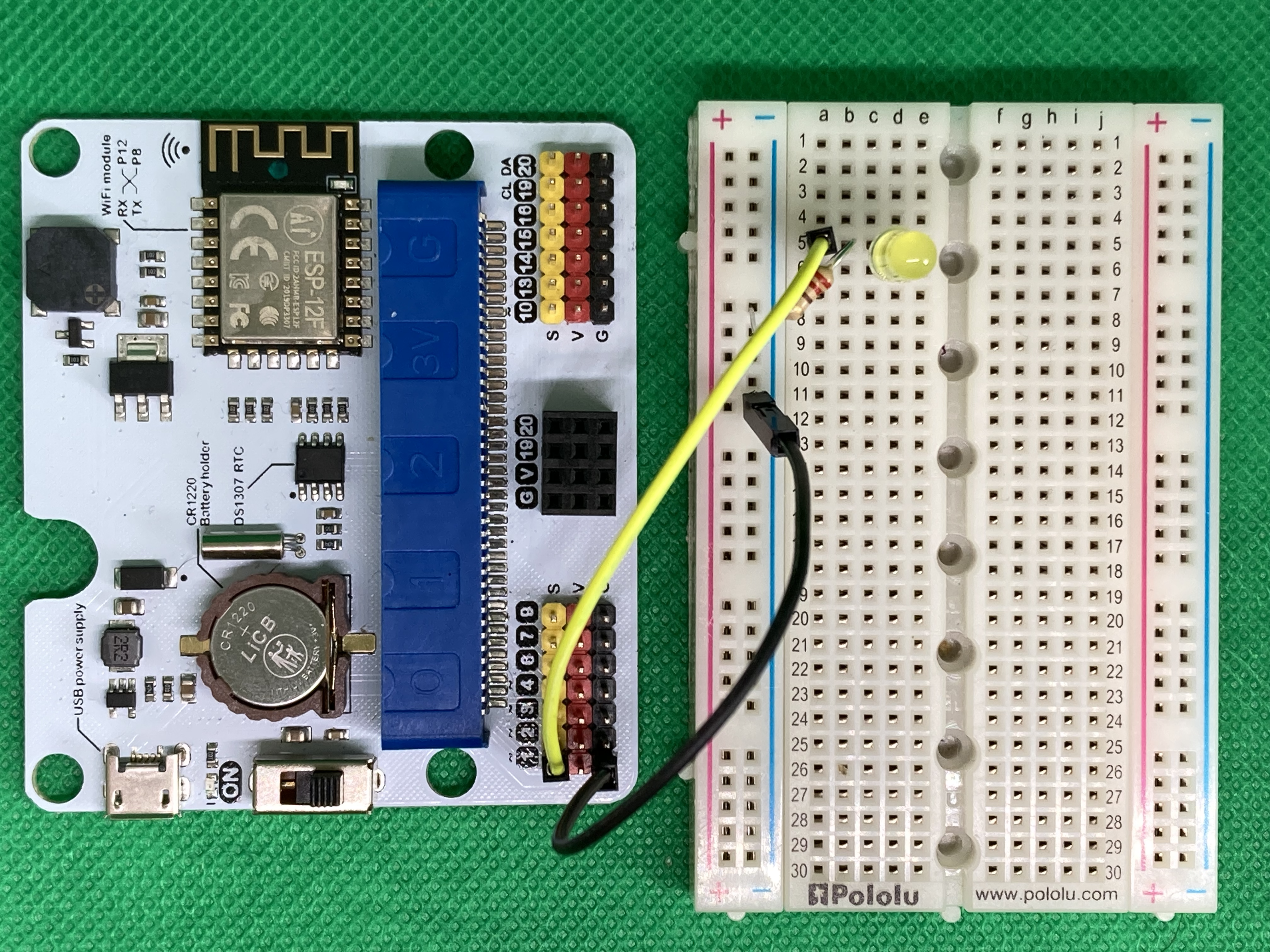
Building an LED Circuit with an ELECFREAKS micro:bit Breakout Board (Or Similar Type)#
Insert the micro:bit into the micro:bit to the breakout board.

Insert the LED into the breadboard.
**Make sure that the LED and the cathode are not on the same row on the breadboard. **
Take note of which lead is the anode.
Tip
Chose a side that the LED lead will always be facing (right or left). This helps prevent incomplete circuits and makes it easier to remember which lead is the anode and which lead is the cathode.
Attach a resistor to the row with the cathode lead of the LED.
Note
The resistor can be attached to either the anode or the cathode in an LED circuit. Pick one lead (either anode or cathode) and attach it to that lead every time an LED circuit is built.

Attach the resistor to a GND pin.
Note
Any GND pin will work on these types of breakout boards. The GND pin does not need to be adjacent to the GPIO pin.
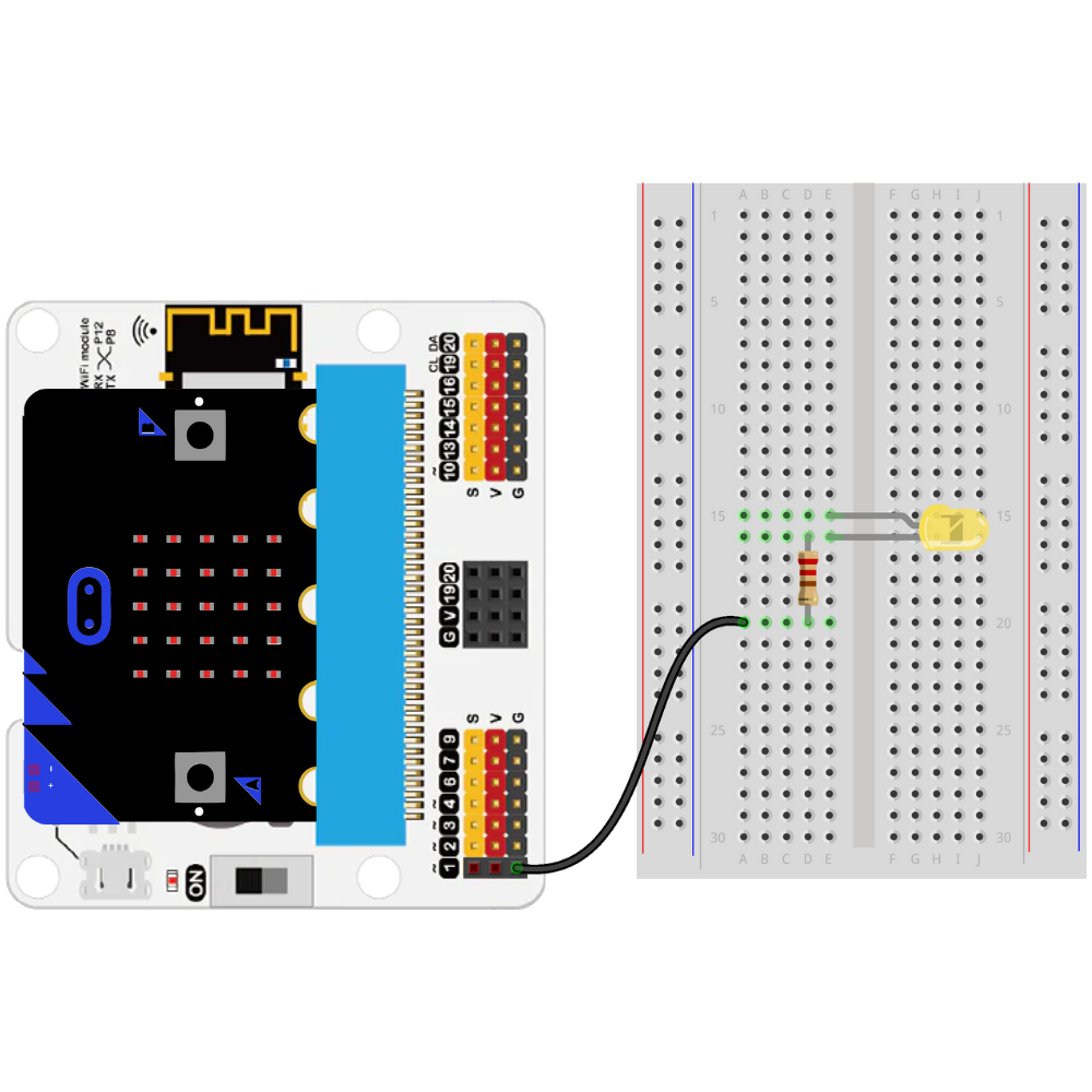
Place a jumper wire from the Pin 1 to the row with the anode.
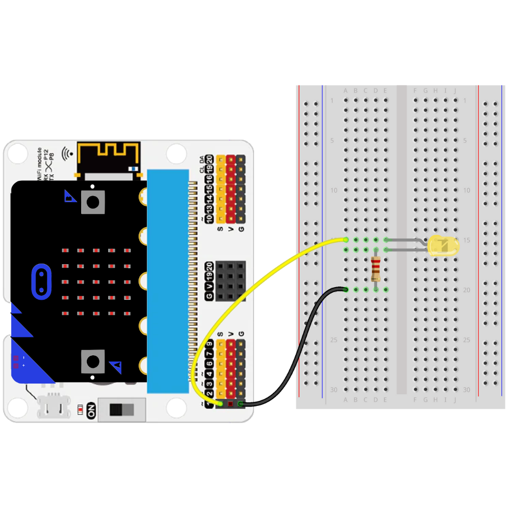
The circuit is complete.
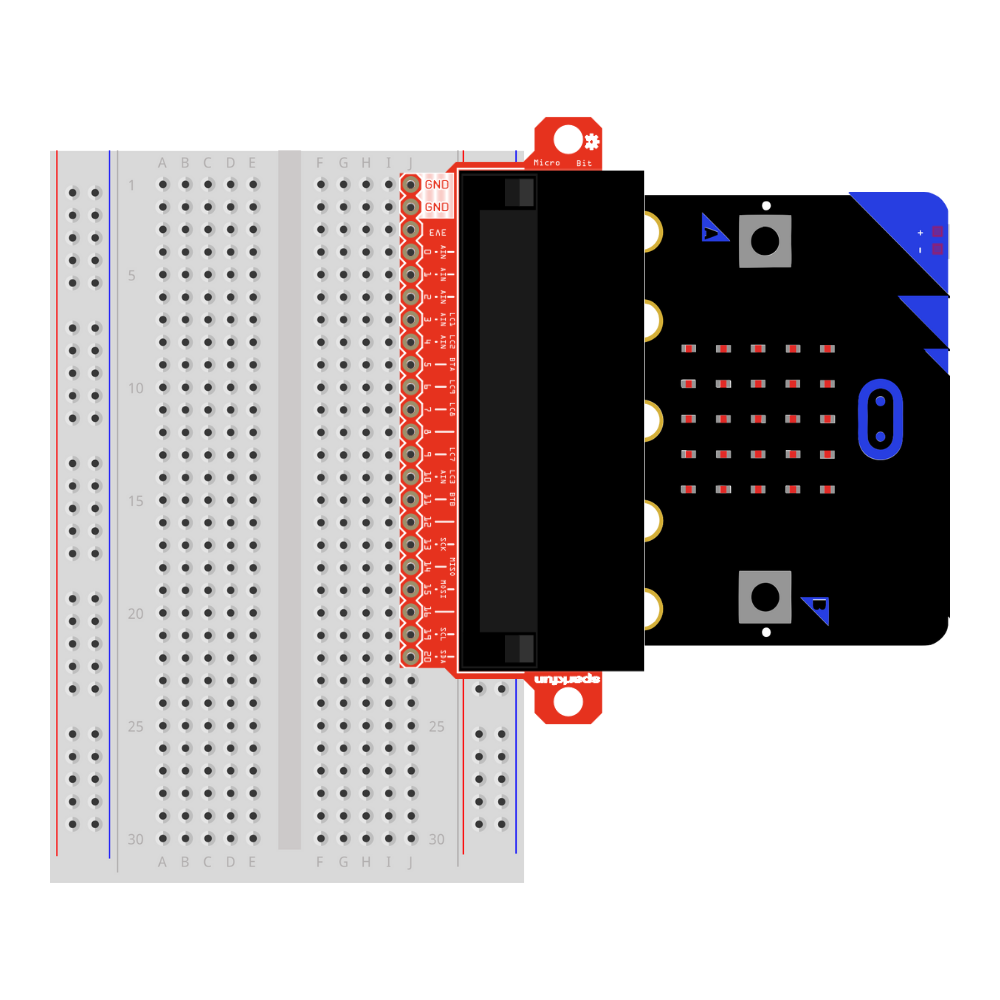
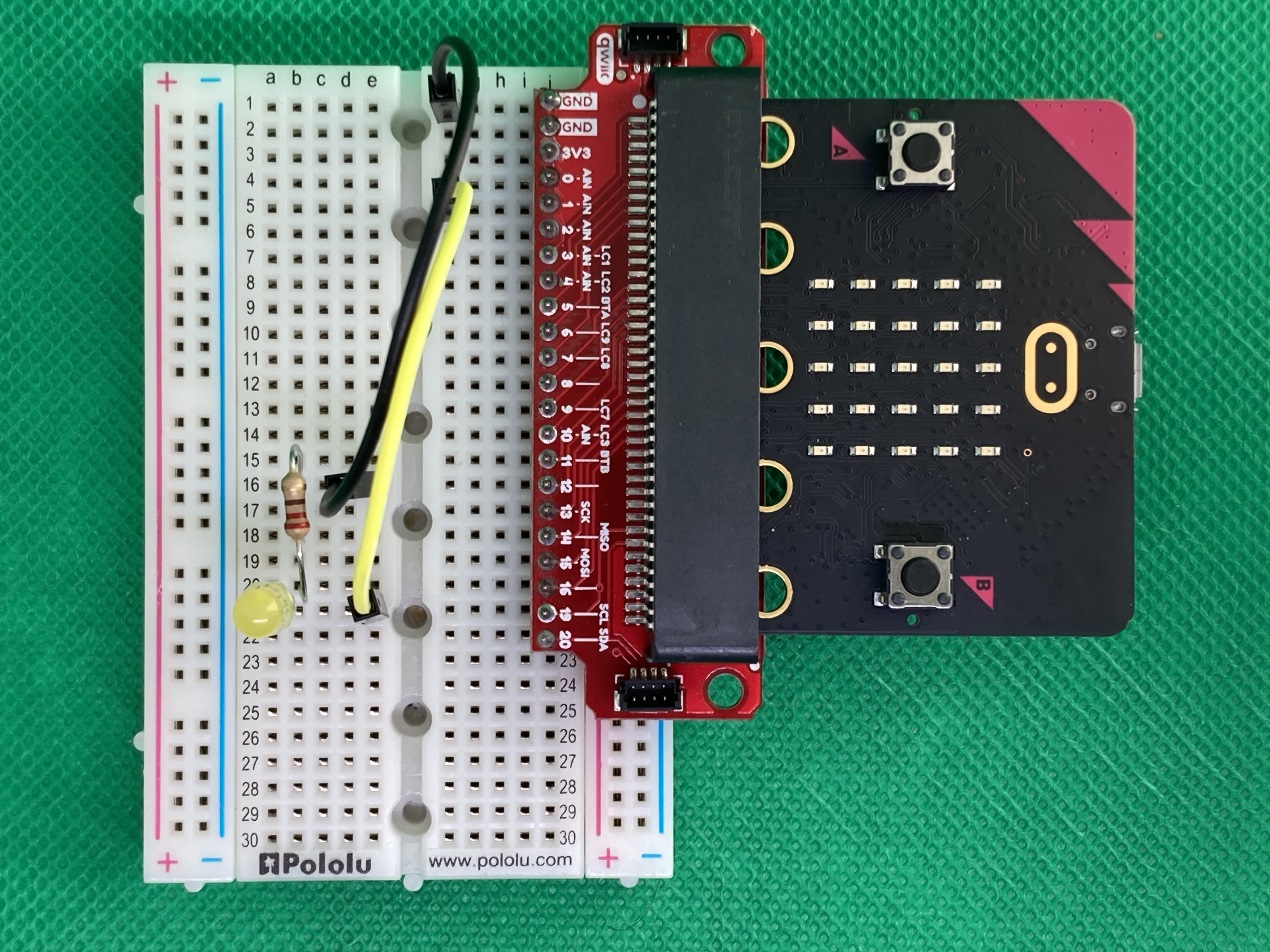
Building an LED Circuit with the SparkFun Qwiic micro:bit Breakout Board (Or Similar Type)#
TODO
TODO
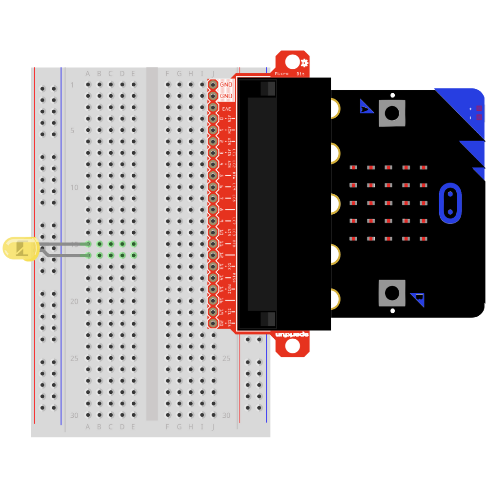
TODO

TODO
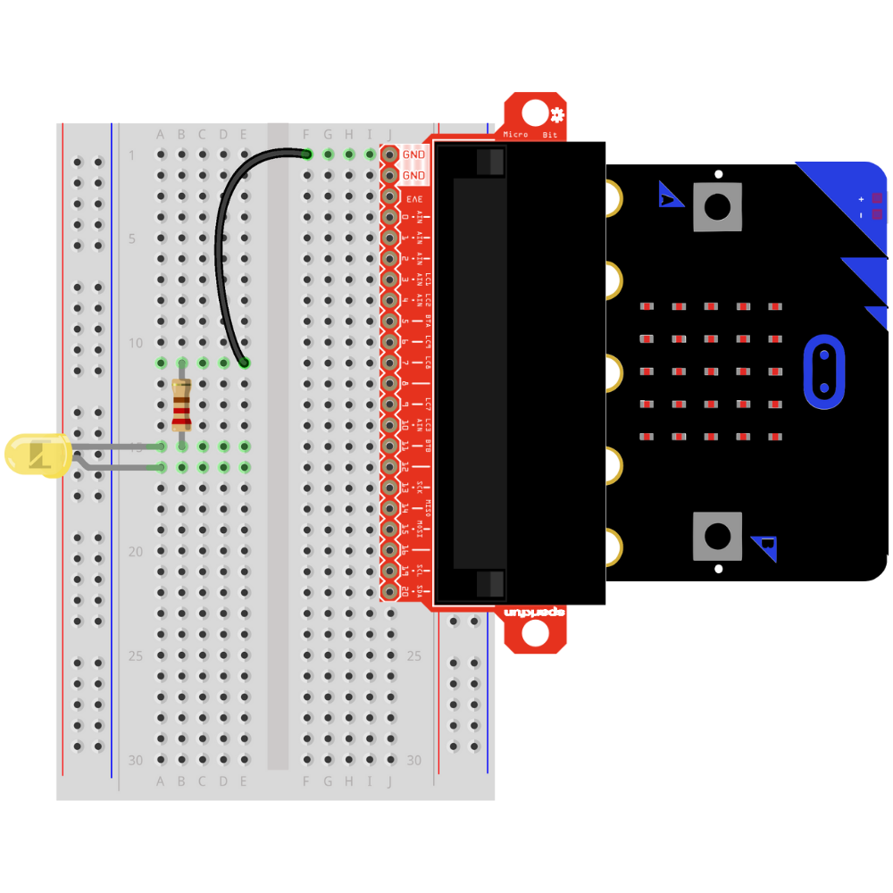
TODO

The circuit is complete.
Troubleshooting the LED Circuit#
If the LED is not illuminating:
Check that the anode and cathode leads are not on the same row on the breadboard.
Check that the GPIO pin is the correct GPIO pin in the code.
Check that the GPIO pin is connected to the anode.
Check that the cathode is connected to GND.
Check that the resistor is connected to the anode and the GND.